
Facehugger – an all-analog, vector-addressable, chainable, function generator.
|
|
||||||||||||||||||||||||||||||||||||||||||||||||||||||||||||||||||||||||||||||||||||||||||||||||||||||||||||||
Current Status:
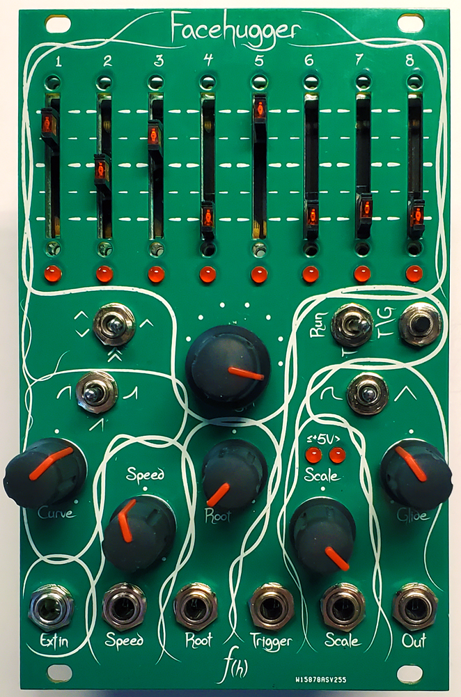
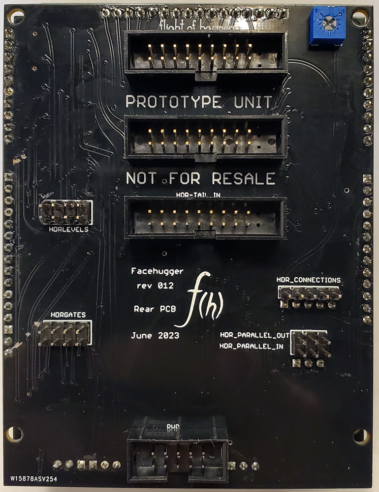
July 6, 2023: The alpha prototype has been built, corrected, and is fully working. The design has been updated and the next circuit board designs are almost complete. The beta and (hopefully) final PCBs will be ordered this week, and test units should be sent out to testers next week.
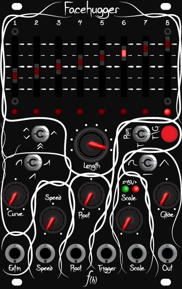
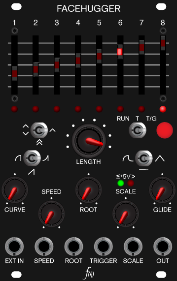
Alternate Utility front panel:
The tendril-style panel is the default on all f(h) modules, but Facehugger has a plain utility-style panel available as well, at no extra cost. Just tell me that you want the Utility panel when placing your order.
The Facehugger module includes:
- Four M3x6 mounting screws and nylon washers
- One 9″ 2×8 Doepfer-style power cable
- One 9″ 2×10 chaining cable
- One 9″ 1×3 parallel cable
What is the Facehugger?
Introducing the Facehugger – an all-analog, phasor-based/vector, non-linear, 8-stage, chainable, control module for eurorack modular synthesizer systems.
What the hell does that mean?
It outputs up to eight different control voltage levels (levels set by the LED sliders) in a sequence determined by a control signal. Depending on how you use it, it can be a:
- Control Voltage (CV) Sequencer
- Gate Sequencer
- Arpeggio Generator
- Envelope Generator
- Burst Generator
- Low Frequency Oscillator (LFO)
The Facehugger is unclocked, using an internal ramp generator to control the cycling, or you can use any external 0-+5V waveform instead. The sequence order is determined by amplitude and polarity of the driving waveform: if it is linear, the stages will trigger linearly (in order), incrementing with a rising signal, and decrementing with a falling signal. With a non-linear drive signal (like a stepped, or staircase wave), the stages will trigger non-linearly based on the same parameters.
Multiple units can be chained together for longer patterns or paralleled for synchronizing to generate chords via rear chaining/paralleling headers.
The rear Ramp out pin can be used as a synch oscillator, or even – when using an external drive waveform – as a separate, fully-controllable LFO with adjustable curvature.
The Facehugger also has a rear expansion header for a separate expander module that provides individual level out jacks, individual gate out jacks, a master Gate in jack, and a ramp out jack.
Features:
Controls:
- Stage level slide potentiometers
- Use to set voltage level of that stage.
- Polarity toggle selects voltage range: up to ±10V for Up & Down,
0 to +10V for Up.
- Polarity toggle selects voltage range: up to ±10V for Up & Down,
-
- LED lights to show active stage.
- Trim potentiometer on PCB to adjust LED brightness
- LED lights to show active stage.
- Use to set voltage level of that stage.
- Length rotary switch
- Rotate to select how many stages per cycle, from 1 to 8.
-
- Row of round LEDs indicates length setting.
- Trim potentiometer on PCB to adjust LED brightness
- Row of round LEDs indicates length setting.
- Polarity & direction toggle switch
- Selects voltage level of Stage level sliders: -10V-+10V for Up/Up and Up/Down, 0-+10V for Up.
-
- Up/Down affects the direction of the cycle:
- Internal Ramp: reverses the direction of the cycle (8-7-6-5-4-3-2-1)
- External signal: selects the Phasor mode, where the stage is selected by the magnitude and polarity of the drive signal. With a bipolar drive signal, the slider order will reverse direction when the drive signal goes + to – or vice versa.
- A positive signal goes 1-2-3-4-5-6-7-8, a negative signal goes 8-7-6-5-4-3-2-1.
- If you have the length set to, say 5, it will be +: 1-2-3-4-5-, -: 5-4-3-2-1.
- A positive-going bipolar ramp from -5V to +5V will have the order 8-7-6-5-4-3-2-1-1-2-3-4-5-6-7-8 (I’ll see about avoiding that center doubling).
- This also inverts the addressing: if +4V = stage 6, -2V = stage 3
- Up/Down affects the direction of the cycle:
- Run/Trigger switch & Trigger pushbutton switch (Internal Ramp only)
- Set to Run to cycle indefinitely, set to Trigger to stop.
- Use for Sequencer mode, or any other continuously looping function
- Set to Run to cycle indefinitely, set to Trigger to stop.
-
- Set to trigger and push momentary Trigger button to run one cycle then stop.
-
- Set to T&G (Trigger and Gate) and push and hold momentary Trigger button to run until button is released.
- Logarithmic/Linear/Exponential curve toggle switch (Log/Lin/Exp) (Internal Ramp only)
- Selects slope of internal ramp drive waveform
-
- Linear: each stage has equal duration
- 1———-2———-3———-4———-5———-
- Linear: each stage has equal duration
-
- Logarithmic: duration increases with each stage
- 1-2–3—-4——5——————-
- Logarithmic: duration increases with each stage
-
- Exponential: duration decreases with each stage
- 1——————-2——3—-4–5-
- Exponential: duration decreases with each stage
- Curve potentiometer (Internal Ramp only)
- Adjusts the amount of curvature of the Logarithmic and Exponential settings (the rate/how much change of increase or decrease between stages)
- Speed potentiometer (Internal Ramp only)
- How fast the internal ramp is and how fast one cycle runs.
- Summed with Speed CV input.
- Root potentiometer
- Set the root note or value the Level sliders are based on
- Use to shift entire pattern around a base note or follow a melody
- Summed with Root CV input
- Scale potentiometer
- Adjust output range from +1V/±1V to +10V/±10V
-
- ≤+5V> indicator LED
- Green when maximum output level is +5V/±5V or less, red when greater than +5V/±5V.
- ≤+5V> indicator LED
- Logarithmic/Linear Glide toggle switch
- Selects output glide curvature
- Logarithmic adds emphasis to end of glide between values.
- Linear creates a smooth blend between values.
- Middle position disables Glide for high speed uses.
- Selects output glide curvature
- Glide potentiometer
- Set the amount of glide or portamento between stages.
- Adjust from none to a smooth ramp
Inputs and Outputs:
- Ext In
- Breaking jack, normalized to internal ramp. Patch your external drive waveform here.
- Disconnects internal ramp, but ramp is still available from rear Ramp output, and is controllable via the Speed and Curve controls & jack.
-
- Note that trigger will not be synchronized to an external waveform. Set Trigger toggle to Run when using an external source for best performance.
- Speed
- CV input to control internal ramp speed.
-
- Summed with Speed potentiometer.
- Root
- CV input to control Root level.
-
- Summed with Root potentiometer.
- Trigger
- Trigger input
- Positive triggered
- Scale
- CV input to control output scaling.
-
- Summed with Scale potentiometer
-
- Usage note: Connect to keyboard aftertouch to add emphasis to a note.
- Out
- System output.
Rear headers:
Chaining header:
- Trigger In
- Alternative trigger signal input
- Trigger Out
- Isolated Trigger output
- State Out
- Gate signal representing state of operation – +5V for running, 0V for not running
- State In
- Used to monitor progress of chained module. 0V off, +5V –> +12V for on
- End Of State (EOS) Out
- +5V trigger fired at end of final stage.
- Chain In
- Input for secondary unit signal to be relayed to Out jack.
- Chain Out
- Copy of Out jack signal
- Ramp Out
- Copy of internal drive ramp. 0 –> +5V
- Scale In
- Scale Out
- Root In
- Root Out
Expansion header:
- Levels 1-8 out
- Gates 1-8 out
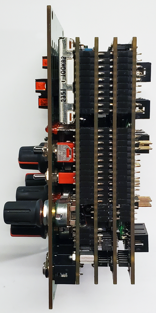
Comparison view (prototype units):
 |
 |
 |