
 |
Technical Specifications:
|
|||||||||||||||||||||||||||||
Plague Bearer Kit:
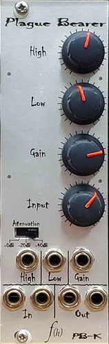
So that everything would fit on one PCB, the Plague Bearer kit differs slightly from the assembled module by omitting the extra CV inputs and aligning the pot to one side. It still has the same functionality. |
||||||||||||||||||||||||||||||
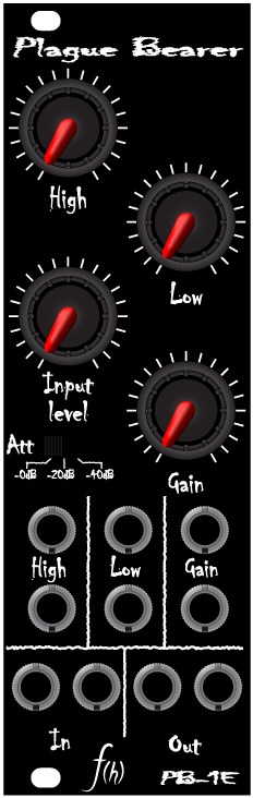
What is the Plague Bearer?The Plague Bearer is called a filter, but that is just a description of the circuit topology, what it can actually do goes way beyond that. It has been described as a filter, a waveshaper, a mangler, a crusher, and – my favorite – as an “FSU module”. I think calling it a filter may be a bit misleading, but I have no idea what else to call it. It is a filter, but it does more (all at the same time, really) excessive phase shifting, waveforming, ringing, formant generation, and so on. I guess it could be called a waveform modifier or enhancer, but those don’t sound good either. I nameed it the Plague Bearer for a reason. If you are looking for technical synthophile specs you are out of luck here. All f(h) devices are designed in accordance with how they sound, not to achieve mathematical perfection. The most common question I receive is, “what is the filter slope?” Honestly, I never measured that. I specifically avoided the conventional approach while I was designing this circuit, so it’s very problematic to try to describe this filter in the normal terms. The slope is directly tied to the gain of the circuit, making it variable, and the Q is affected by all three filter controls. The setup is actually a combined High- and Low-pass. The corner frequencies are adjusted by the controls and can be overlapped completely, which gives a comb-filtering effect.
|
||||||||||||||||||||||||||||||