


Prototype Image Gallery here
Pricing (USD):
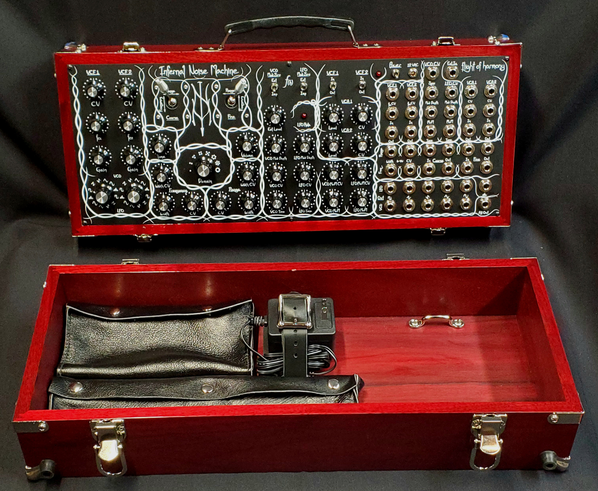
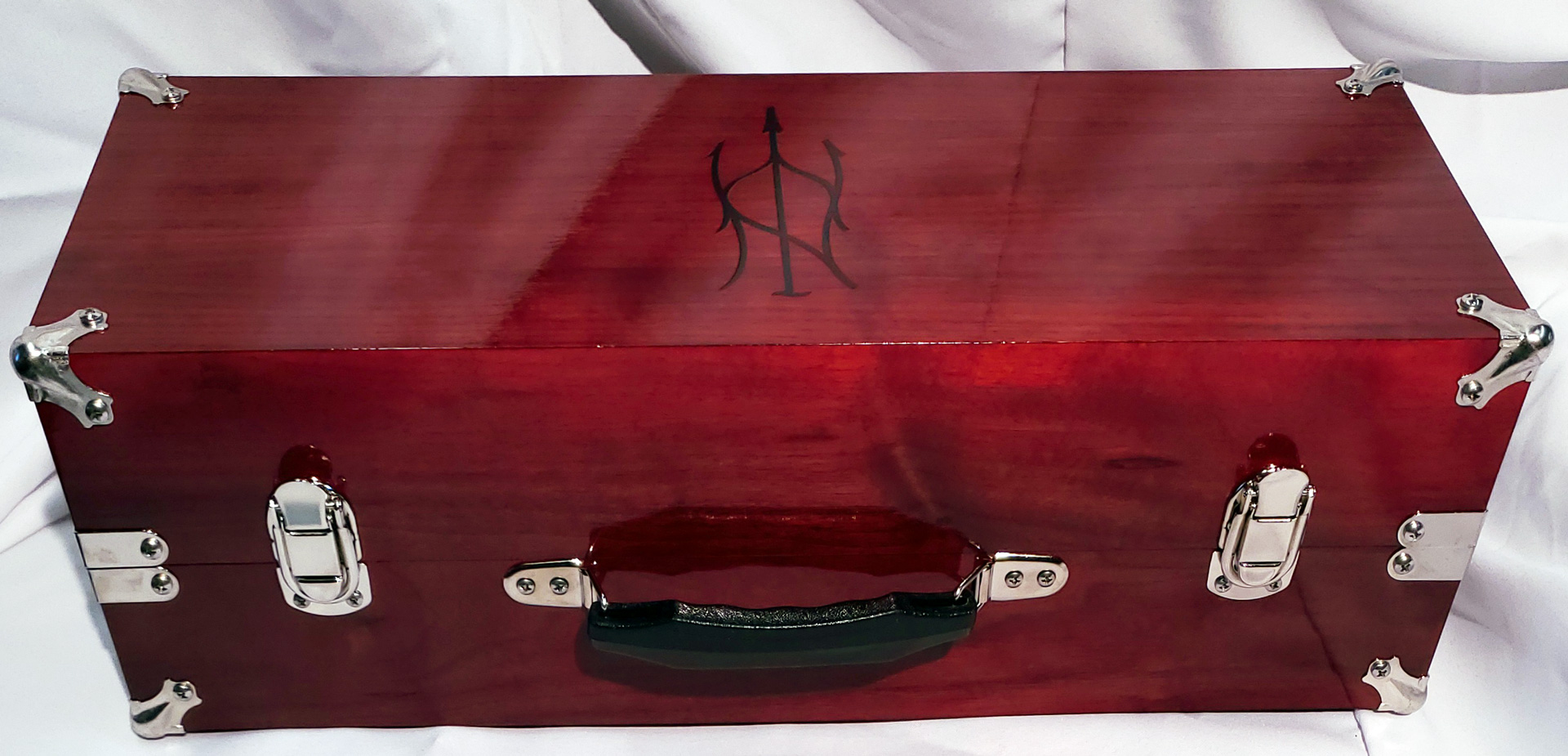
Blood Box road case: $2,366.00
-Material: Black Walnut (see note), stained, nickel-plated hardware.
-Dimensions: 20″W x 10″H x 7″D (closed)
-Weight: ~13lbs.
Minimal case: $1,916.00 (No hardware or stain, just four feet and a protective top coat.)
-Material: Black Walnut (see note)
-Dimensions: 20″W x 9″H x 4.5″D
-Weight: ~10lbs.
*Note: Case sides are solid black walnut. Top & bottom are Black walnut plywood for dimensional stability (so the box won’t split due to temperature or humidity fluctuation).
Both include a US AC adapter (12VAC 1500mA, 5.5mm x 2.1mm). For international orders, deduct $20 from the price and I will locate a compatible adapter in or near your country that you can order, if needed. Blood Box also includes the related tiedowns, anti-vibration pad, and leather strap.
Free Options :
Jacks (choose one): 1/4″, 3.5mm, banana. For banana, let me know your preferred color scheme. A ground jack will also be added in the top right of the panel.
Minimal case:
For the finish coat, choose either a gloss polyurethane or a satin-ish wax. The poly really brings out the grain and color and protects the wood very well, while the wax gives a soft and warm tone to the wood and is (in my opinion) much more pleasant to the touch.
Add-ons:
Storage pouches: (Images in gallery)
- 8″W x 4″H: $55
- 13.5″W x 3.25″H: $60
- 8″W x 7″H: $65
- 5.5″W x 3.25″H: $50
Basic combinations: 1 A and 1B, 1 C and 1 D, 1 A and 2 D. (A&B shown)
Tie down points (Footman loops): $5 each, let me know how you’d like them arranged.
Custom pouches and straps available, just ask!
Ordering:
Send me an email with the details, requests, and any questions, for your order at flight (at) flightofharmony (dot) com.
Payment will be via Paypal.
Demo videos:
Description and specifications:
| Type | Sound source/Oscillator Paraphonic, semi-modular synthesizer CV & Signal processor |
| Format | Desktop/Standalone |
| Dimensions | Without Lid: 21” Wide, 9” High, 3.5” Deep |
| Power | 12VAC, 1500mA wall adapter 2.1mm x 5.5mm barrel jack |
| Mechanical life | Joysticks: 300k cycles. Potentiometers: 100k cycles. Jacks: Min. 10k cycles. |
Original Desktop Infernal Noise Machine
Eurorack Infernal Noise Machine (INM-E)
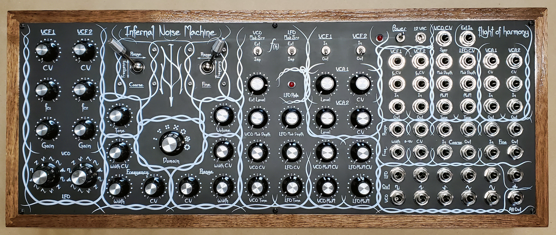
The INM-D retains the semi-modular (a.k.a., normalized) arrangement as before, with the IMP noise core, VCO, VCLFO, VCF, and VCA sections able to be used separately with other devices, or by inserting other devices into the signal chain of the INM itself.
In addition to all the features of the previous versions, several new capabilities are added to the INM-D and the VCO and VCLFO are completely independent, with outputs and controls always available.
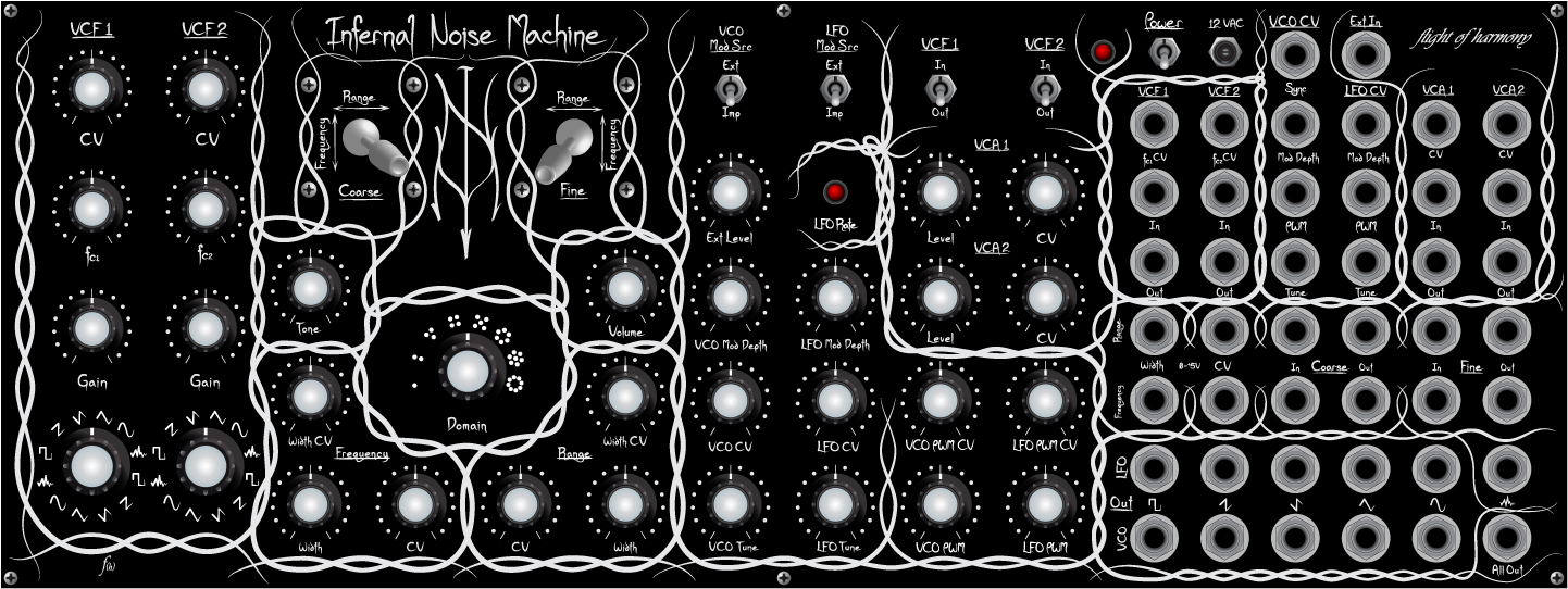
The grouping of the jacks follows the layout of the controls.
Each VCF has (all ±5V): one CV input for the Center Frequency of the filter, one breaking audio Input, and one breaking audio Output.
Each VCA has (all ±5V): one input for the Output Level, one breaking audio Input, and one non-breaking audio Output. VCA1 and VCA2 are also averaged and sent to All Out
The VCO has:
Inputs (all ±5V): hard Sync, Modulation Depth, Pulse Width Modulation, Tune/frequency.
Outputs (all ±5V): Square, Ramp, Saw, Triangle, Sine.
The VCLFO has:
Inputs (all ±5V): Modulation Depth, Pulse Width Modulation, Tune/frequency.
Outputs (all ±5V): Square, Ramp, Saw, Triangle, Sine.
The External In input jack is shared by the VCF and VCLFO.
The IMP is controlled by the joysticks, which can also be used to control anything else they are connected to.
The IMP ±5V audio output is the Noise out jack just above the All Out jack in the bottom right
The 0->+5V CV inputs for the IMP are:
Range Width, Range CV, Frequency Width, Frequency CV.
The Coarse and Fine joystick Outputs provide either the 0->+5V signal that is sent to the IMP, or whatever signal is supplied to the respective Input, with the joysticks working as attenuators.

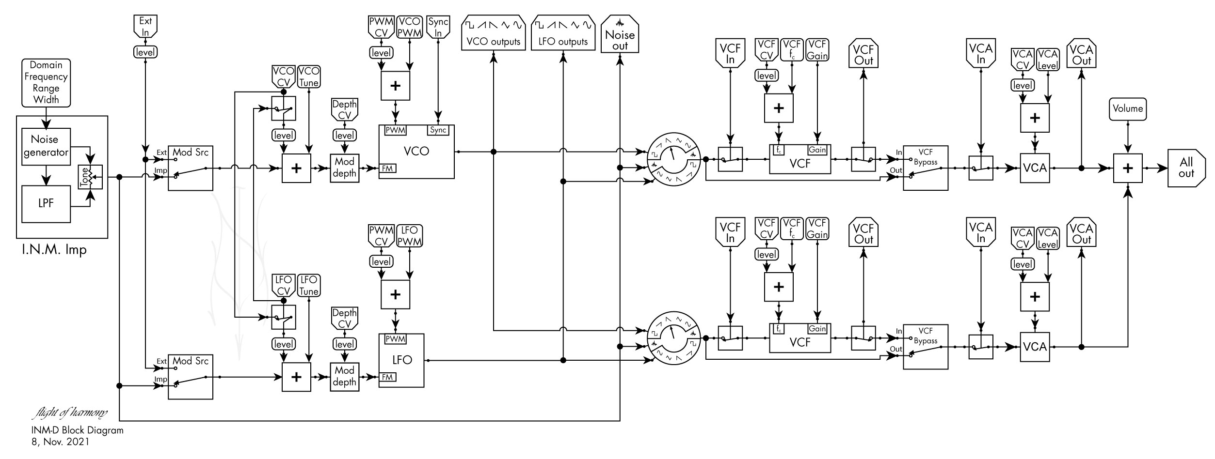
- Functional Features
- IMP noise core audio source, generated by the nonlinear heterodyning of a pair of oscillators. The IMP has eight frequency regions (Domains) of operation, from semi-random sub-audio impulses to above audio range, used as the primary frequency modulation (FM) source for the VCO and LFO. The output is also available to each signal chain as well as an independent output jack.
Frequency of oscillation is controlled by Coarse and Fine joysticks with multiple Control Voltage (CV) inputs and other controls. The joysticks have breaking input jacks for controlling external signals, and non-breaking output jacks to allow the signal to be used externally as well as control the IMP.
- IMP noise core audio source, generated by the nonlinear heterodyning of a pair of oscillators. The IMP has eight frequency regions (Domains) of operation, from semi-random sub-audio impulses to above audio range, used as the primary frequency modulation (FM) source for the VCO and LFO. The output is also available to each signal chain as well as an independent output jack.
- Voltage-Controlled Oscillator (VCO)
- 1 Volt per Octave (1V/Oct) covering ~19Hz to ~44kHz.
- Temperature-compensated
- Square, Ramp, Saw, Triangle, and Sine, waveforms outputs available to each signal chain along with independent output jacks for each waveform.
- Hard Synchronization input.
- Resets VCO at each input pulse.
- Pulse Width Modulation (PWM) on Square wave.
- Dial and CV control.
- Shared CV with LFO:
- A plug inserted into the VCO CV input jack will send its signal to both the VCO and LFO until a plug is inserted into the LFO CV input jack. This can be adjusted using the LFO CV dial.
- A plug inserted into the LFO CV input jack will send its signal to both the LFO and VCO until a plug is inserted into the VCO CV input jack. This can be adjusted using the VCO CV dial.
The VCO can be modulated by the internal IMP noise core or by the external modulation source, and the modulation amount (depth) of either can be controlled by dial and CV.
- 1 Volt per Octave (1V/Oct) covering ~19Hz to ~44kHz.
- Voltage-Controlled Low-Frequency Oscillator (VCLFO, but called just LFO here to simplify)
- L~750Hz down to ~0.0015Hz (~11 minutes per cycle).
- Shared CV with VCO:
- A plug inserted into the VCO CV input jack will send its signal to both the VCO and LFO until a plug is inserted into the LFO CV input jack. This can be adjusted using the LFO CV dial.
- A plug inserted into the LFO CV input jack will send its signal to both the LFO and VCO until a plug is inserted into the VCO CV input jack. This can be adjusted using the VCO CV dial.
The LFO can also be modulated by the internal IMP noise core or by the external modulation source, and the modulation amount (depth) of either can be controlled by dial and CV.
- 2 Audio signal chains consisting of a Voltage-Controlled Filter (VCF) (bypassable) and a Voltage-controlled Amplifier (VCA), each with breaking inputs and outputs (I/O). These I/O allow the VCF and VCA to be used independently or as inserts to the signal chain to allow external effects to be added. The two VCA outputs can also be used to provide stereo imaging and effects.
- VCF Source selection continuous-rotation rotary switches to select a waveform from either the VCO or VLFO to send to each signal chain.
- The VCF are Voltage-Controlled Bandpass Filters (VCBPF). Filter bandwidth and Gain are varied by the Gain control and the filter’s Center Frequency is varied by the fc control and can also be voltage-controlled.
- The VCF In/Out bypass switches remove the filters from the signal chain to pass the raw modulated VCO signal to the VCA.
- The VCAs have ±5V “soft-knee” output limiting protection for external modules. Instead of hard clipping, which squares-off the peaks of the signal, the soft-knee performs a gradual limiting of the signal as it approaches ±5V.
- Summed output of VCA 1 & VCA 2 available at the All Out jack, via the Volume control.
- Sections
- VCF1&2
- Controls
- CV
- Center Frequency control voltage input attenuator
- fc
- Center Frequency
- Gain
- Gain level
- Source
- VCO/LFO source waveform selector (bypassed by using Ext In Jack)
- VCO in upper half, LFO in lower half.
- VCO Square
- VCO Ramp
- VCO Saw
- VCO Triangle
- VCO Sine
- Noise
- LFO Square
- LFO Ramp
- LFO Saw
- LFO Triangle
- LFO Sine
- Noise
- CV
- Selector switches (In VCA section)
- In/Out
- Have VCF either In or Out of VCF →VCA signal chain (Bypass)
- In/Out
- Inputs
- fc CV, ±5V
- VCF center frequency
- Buffered
- Ext In, ±5V
- External signal input
- AC-coupled
- Breaking
- External signal input
- fc CV, ±5V
- Outputs
- Out, ±5V
- AC-coupled
- Breaking
- Out, ±5V
- Controls
- IMP noise core
- Controls
- Frequency & Range Joysticks
- Coarse
- Fine
- Domain rotary switch
- Select frequency band of IMP noise core
- 1-8, lowest → highest
- Tone
- Low-pass filter to remove harshness in higher domains
- Frequency
- Width
- width of Frequency band affected
- Frequency control voltage input attenuator
- Width control voltage input attenuator
- Width
- Range
- Range control voltage input attenuator
- Width
- width of Range band affected
- Width control voltage input attenuator
- Frequency & Range Joysticks
- Inputs
- CV, 0→+5V
- Over- and under-voltage protection
- Frequency and Range control voltage (buffered)
- Coarse Frequency and Range (Joystick)
- Fine Frequency and Range (Joystick)
- Frequency and Range Width (no attenuator)
- CV, 0→+5V
- Outputs
- CV, 0→+5V
- Coarse Frequency and Range
- Joystick, buffered, non-breaking
- Fine Frequency and Range
- Joystick, buffered, non-breaking
- Coarse Frequency and Range
- Signal, ±5V
- Noise out
- ±5V soft-clip limited
- CV, 0→+5V
- Controls
- VCO
- Controls
- VCO Tune
- VCO frequency
- VCO CV
- VCO frequency control voltage attenuator
- VCO Mod Depth
- Depth modulation signal affects VCO
- Ext Level
- External VCO modulation signal input attenuator
- VCO Mod Src toggle switch
- Select either Internal or External VCO modulation source
- VCO PWM
- Pulse Width Modulation level
- VCO PWM CV
- PWM control voltage attenuator
- VCO Tune
- Inputs, ±5V
- Tune
- VCO frequency control voltage
- PWM
- PWM control voltage
- Mod Depth
- VCO Modulation Depth control voltage
- Sync
- Synchronization signal
- Hard synchronization
- Ext
- External modulation source
- Shared with LFO
- AC-coupled
- ±5V soft-clip limited
- Tune
- Outputs, ±5V
- Square
- Ramp
- Saw
- Triangle
- Sine
- Controls
- LFO
- Controls
- LFO Tune
- LFO frequency
- LFO CV
- LFO frequency control voltage attenuator
- LFO Mod Depth
- Depth modulation signal affects LFO
- Ext Level
- External LFO modulation signal input attenuator
- LFO Mod Src toggle switch
- Select either Internal or External LFO modulation source
- LFO PWM
- Pulse Width Modulation level
- LFO PWM CV
- PWM control voltage attenuator
- LFO Tune
- Inputs, ±5V
- Tune
- LFO frequency control voltage
- PWM
- PWM control voltage
- Mod Depth
- LFO Modulation Depth control voltage
- Ext
- External modulation source
- Shared with VCO
- AC-coupled
- ±5V soft-clip limited
- Tune
- Outputs, ±5V
- Square
- Ramp
- Saw
- Triangle
- Sine
- Controls
- VCA 1&2
- Controls
- Level
- CV
- VCA output level control voltage input attenuator
- Inputs, ±5V
- CV
- VCA level
- Buffered
- CV
- In
- External signal input
- Breaking
- External signal input
- Outputs, ±5V
- Out
- Signal out
- ±5V soft-clip limited
- Non-breaking
- Signal out
- Out
- Averaged Output
- Control
- Volume
- Output, ±5V
- All Out
- Averaged output of VCA1 & VCA2
- ±5V soft-clip limited from VCAs
- Averaged output of VCA1 & VCA2
- All Out
- Control
- Controls
- VCF1&2